
This page presents selected examples of work and developments carried out by ICSS on both industrial processes and control systems. These case studies cover HRSG control, diagnostics of ALSPA P320 architectures, IEC 60870-5-101 communications, long-term operational support for obsolete systems, reverse engineering, and the development of tailored electronic and software solutions.
Process and control
Secure feedwater distribution between two valves
Online redesign of drum-level control and distribution of a common demand between a low-flow valve and a main valve, with bumpless transfer and an operator rollback option.
Kwinana (Perth, Australia) — KA13E2 combined-cycle power plant (320 MW)
Context
The modification had to be commissioned on a unit in commercial operation. The priority was therefore not only to improve control: it had to be possible to activate the new concept progressively, observe its behaviour and immediately return to the previous logic if it had an undesirable effect on the process.
The ALSPA P320 control-system diagrams were supplemented with an activation selector available to operators. The new demand distribution could therefore be validated under controlled conditions without removing the rollback option.
Limitations of the initial control strategy
Each boiler drum had two feedwater valves: a low-flow valve known as the “30%” valve and a main valve known as the “100%” valve. The initial concept used four PID controllers and controlled the two valves independently:
- One PID converted the level error from one-element control into an opening demand for the 30% valve only.
- Two flow PIDs, one for each valve, converted the flow setpoint from three-element control into opening demands.
- One three-element level PID calculated the common flow setpoint sent to both flow loops.
In this architecture, the main valve never participated when three-element control was unavailable. A flow-measurement fault, for example, caused a fallback to one-element control limited to the small valve. At high load, the available flow could then become insufficient to maintain drum level and could trip the boiler.
Overall demand and allocation between valves
The new architecture uses only three PIDs to produce an overall demand common to both valves: one PID for one-element control and two PIDs — level and flow — for three-element control. The three-element loop continues to track the one-element loop to prepare a consistent transfer between the two modes.
Allocation logic then converts this overall demand into individual setpoints. The small valve supplies low flows; the main valve takes over as demand increases. Both valves are open simultaneously only within the transfer zone, providing a bumpless changeover. In manual mode, the operator still acts on a single opening demand, which is automatically distributed between both actuators.
Associated tracking and protections
The redesign also made transient states more consistent:
- The level section of three-element control tracks the difference between steam flow, drum-feedwater flow and attemperation flow during a feedwater-pump switchover or while the pressure limiter is active.
- The flow section of three-element control tracks the common demand when this mode is inactive, during a pump switchover or under limiter action.
- One-element control tracks the common demand when valve opening is controlled manually.
- Three-element control is disabled if either valve is switched to manual or if gas-turbine flame detection is lost.
- The economiser pressure limiter acts directly on the common demand. When pressure falls back below the setpoint, its high limit is briefly reset to the current demand level to improve response time.
Result
The main valve is now available in every drum-level control mode. Falling back to one-element control no longer artificially reduces feedwater capacity, valve transfers are controlled and manual operation remains simple. The reversible logic allowed online commissioning with controlled risk.
Coordinate the multi-stage attemperators of an HRSG
Redesign of attemperator control to coordinate two injection stages and feedwater pressure during rapid HRSG transients, particularly during the transition to low-load operation, while keeping steam-turbine stress within its limits.
Niehl 3 (Cologne, Germany) — KA26 combined-cycle power plant (450 MW) with district heating
Initial problem
The HRSG has two attemperation stages. The first, located before the final superheater, responded very slowly in order to progressively reduce the action of the second attemperation stage. The latter, located after the superheater, provided fast correction of steam temperature at the boiler outlet.
In practice, the first stage never closed completely and sprayed too much water for too long. The concept became particularly unsuitable during rapid gas-turbine transients.
When low-load operation was activated, gas-turbine load had to be greatly reduced while keeping the steam turbine connected. Steam temperature then had to decrease progressively to keep thermal stress on the steam turbine within permissible limits.
This gas-turbine load reduction nevertheless caused significant HRSG transients. The initial control strategy did not sufficiently coordinate the two attemperation stages and feedwater pressure to follow these changes. Steam temperatures could then deviate from their trajectory, sharply increase steam-turbine stress and trip the turbine unless operators took manual control of the attemperators.
The variable-speed feedwater pumps had not been integrated into the strategy either. When drum pressure remained low while gas-turbine load increased rapidly, fully opening the attemperator valves no longer guaranteed the required injection flow. Temperature then also had to be controlled through feedwater pressure. This variable pressure also had to be considered in the PID-loop gain and integral settings.
New coordination of both stages
The first-stage setpoint was completely recalculated so that it would contribute during transients without assuming final temperature control:
- The setpoint is limited between 450°C and 588°C; the high limit remains compatible with piping protection.
- When the boiler-outlet temperature setpoint is below 555°C, the first stage targets 565°C to limit its spraying time while remaining available during a rapid load increase.
- Above 555°C, its setpoint is placed 10°C above the final setpoint, leaving the final stage responsible for precise control at the boiler outlet.
- If the final stage exceeds 75% opening, an additional PID progressively lowers the first-stage setpoint to request more contribution. This correction proved particularly useful on intermediate-pressure steam, supplied by the low-pressure stage of the feedwater pumps.
Parameters adapted to the operating point
With this new distribution of roles, the first stage must remain closed as much as possible, but become highly responsive when approaching the final-superheater temperature limit. The PID parameters were therefore revised.
Automatic adjustment also adapts the parameters to the instantaneous difference between steam and feedwater pressure. While the first stage is still stabilising and its temperature error becomes significant, the final-stage parameters are temporarily strengthened to retain a fast response at the boiler outlet.
Anticipating rapid load increases
A predictive command was added to the first stage so that the PID alone would not have to absorb a rapid increase in gas-turbine load:
- When temperature exceeds the setpoint by 5°C, a calculated opening is applied to the first stage, its setpoint is lowered to allow rapid PID recovery, and a progressive demand to increase feedwater pressure is initiated.
- If the error persists for more than ten seconds, an additional pulsed command is calculated from the temperature error.
- Above 590°C, a safety opening and a more aggressive feedwater-pressure increase are provided; this protection was not called upon during testing.
- Above 600°C, the feedwater pump is accelerated to maximum speed.
- When the first stage exceeds 98% opening, the final-superheater outlet temperature is controlled directly through feedwater pressure.
Transfer zones between the two final-stage valves and several secondary parameters were also adjusted during commissioning tests.
Results
Under normal operating conditions, steam temperature is controlled more quickly and accurately. The first stage opens only when it makes a genuine contribution, reducing unnecessary spraying periods and leaving final temperature control to the last stage.
During transitions to or from low-load operation, the HRSG follows rapid gas-turbine changes without manual operation of the attemperators. Combined-cycle low-load operation was reached faster than expected, with greatly reduced stress on the steam-turbine side.
Control systems
Diagnose and contain an intermittent MFC1000 switchover
Investigation of an intermittent fault affecting a redundant ALSPA P320 Series 6 architecture, followed by adaptation of monitoring and timing to prevent a unit trip during an unintended switchover.
Angostura (Biobío, Chile) — Hydroelectric power plant (318 MW)
An intermittent fault with no usable trace
A hydroelectric unit experienced intermittent trips accompanied by an unexplained restart of the master MFC1000 controller and switchover to the standby controller. The logs contained no cause before the restart, and the recorded chronology was partially distorted by the switchover itself, making the fault particularly difficult to locate.
It was necessary to distinguish a redundancy malfunction from a very brief event occurring immediately before the switchover, while securing operation without masking the root cause.
Reconstruct the actual sequence
ICSS correlated events timestamped by the field controllers, operating histories, MFC1000 logs and equipment behaviour. Opening of the generator circuit breaker, activation of the trip relay and start-up of the oil-injection pumps strongly indicated a transient loss of the hardware watchdog signal.
This loss could have been caused by logic executed immediately before the switchover or by a momentary interruption of EPL exchanges with an I/O controller. The difficulty lay precisely in the event’s short duration: the MFC1000 restarted before it could retain the cause in its own logs.
Rule out a fault in normal switchover operation
Tests were performed involving normal switchover, loss of the networks and EPL interfaces, and loss of MFC1000 power. None reproduced the trip: in these situations, redundancy operated correctly, the standby controller took over the application and the unit remained in service.
These tests focused the investigation on a very brief loss of the watchdog or I/O data rather than on the normal redundancy mechanism.
Secure operation and make the fault observable
A watchdog delay in the logic and a time-delay relay were added to filter losses too brief to justify a unit trip. This protection does not disable the safety function: it prevents a transient discontinuity that is compatible with recovery by the redundant controller from being interpreted as a permanent loss of control.
New logic directly records the state of the physical watchdog output. Automatic log-collection tools and continuous network captures were also deployed so that any recurrence could be analysed using the traces missing from the initial events.
Restore compliance of the EPL architecture
The EPL configuration was compared with the hardware actually installed and the expected redundant architecture. The relevant controllers were regenerated and reloaded with a consistent configuration, then several EPL components exhibiting intermittent faults were replaced.
The work therefore combined configuration correction, treatment of suspect components and improved observability, rather than simply increasing a delay without understanding the trip chain.
Result
Transient losses are now filtered while redundancy takes over, whereas permanent faults continue to trigger the expected safety response. The EPL configuration matches the installed architecture, and the diagnostic facilities retain the chronology, logs and captures required if another event occurs.
Restore reliable recovery after IEC 101 communication loss
Diagnostics of a Centralog Series 5 chain with CSS-G IEC 101 and SPT4-NET that exhibited degraded data after reconnection, followed by a reduction in general-interrogation time from more than 2 min 20 s to approximately 20 s.
Sønnå (Sauda, Norway) — Hydroelectric power plant (212 MW)
Context
Alarms and degraded-quality values appeared at the control centre after certain losses and restorations of the IEC 60870-5-101 serial link. The fault was intermittent and appeared more frequent during unit start-up or shutdown, although no single physical cause could be reproduced during the assignment.
Diagnostics combined CSS-G traces, network captures, disconnection and reconnection tests, and analysis of the SPT4-NET converter’s internal operation. It is not a simple transparent adapter: it polls the remote equipment at different frequencies and maintains an internal data image to respond quickly to requests from the master system.
At protocol level, the analysis also covered the exchanged ASDUs, their causes of transmission (COT), common addresses, information-object addresses (IOA) and quality descriptors associated with single-point information and measured values.
Functional cause
After a loss of IEC 101 communication, the SPT internal image could be invalidated without being rebuilt immediately. Analogue values progressively recovered, but some digital states could remain invalid until replaced by a new event.
In IEC 60870-5-101 terminology, reconstruction relied in particular on a C_IC_NA_1 general interrogation, followed by recovery of the indication and measurement ASDUs: M_SP_NA_1 and M_DP_NA_1 single- or double-point information, and M_ME_NA_1, M_ME_NB_1 or M_ME_NC_1 measured values according to their encoding. Consistency of quality descriptors and causes of transmission was as important as the value itself.
The general interrogation used to rebuild this image took more than 2 min 20 s. During that period, commands and setpoints could remain pending. A periodic general interrogation every ten minutes also unnecessarily recreated a window of degraded data during normal operation.
Corrections made to the existing chain
- Consistent increase in IEC 101 speed from 9,600 to 19,200 baud on the CSS-G and SPT sides.
- Increase in maximum frame length from 100 to 255 bytes.
- Removal of periodic general interrogation and triggering of a complete reconstruction after timeout or reconnection.
- Adaptation of quality handling during an interrogation so that data simply being refreshed are not declared offline.
- Periodic retransmission of analogue values and correction of setpoint-termination handling.
- Reduction of trace volume and preparation of capture tools to facilitate future diagnostics without disturbing the gateway.
Result
IEC 101 general-interrogation time fell from more than 2 min 20 s to approximately 20 s. Communication-loss and recovery tests, supplemented by overnight monitoring, demonstrated correct data reconstruction and satisfactory operation of the existing chain.
Because IEC 60870-5-101 and IEC 60870-5-104 share the same application model and ASDU families, this diagnostic method remains applicable to serial architectures, serial/IP gateways and multi-vendor communication chains.
Maintain an ALSPA P320 Series 4 system rather than replace it prematurely
Restoration of Controcad engineering facilities, virtualisation of legacy workstations, contracted maintenance, spare-parts management and recovery of the ability to modify an ALSPA P320 Series 4 installation.
Tavaux (France) — Industrial cogeneration plant (2 × LM6000), ALSPA P320 Series 4
Context
Since 2019, ICSS has supported the teams at the Tavaux industrial site with maintenance and development of the control system for their cogeneration unit.
During the initial discussions, replacing the ALSPA P320 system appeared to be the natural response to its age. Analysis of the requirement showed that a complete retrofit would require a significant budget while the plant’s remaining operating life was uncertain. One unit has since been dismantled.
The selected strategy was therefore to restore genuine maintainability of the existing system and then organise long-term support. This approach does not systematically oppose maintenance and retrofit: it adapts investment to the remaining industrial life and risks actually observed.
Recover engineering capabilities
ICSS virtualised the P4 engineering workstation under Windows NT and restored the legacy Controcad Unix environment under Solaris. Projects, generation tools and loading facilities were restored, enabling network transfers to P4 and microETE.
This restoration does more than preserve a backup of the existing system. It now makes it possible to modify the C370 control logic, regenerate its code and load new changes. Time-delayed alarms, for example, were recently added in Controcad, then loaded and tested on the controllers and Centralog HMI.
Remove fragile dependencies
- Replacement of DAT-drive backups with network transfer of HDSR archives to the P4 virtual machine.
- Adaptation of Solaris and JetAdmin scripts to reinstall modern printers automatically after a restart.
- Maintenance and modification of the CLOGSQL interface with the performance-calculation system and peripheral workstations associated with the process.
Maintenance, redundancy and spare parts
The maintenance contract covers CCC, CIS, CVS and operator workstations, redundant C370 controllers, F8000, F900 and Contronet networks, CE2000 equipment and associated boards. Visits include implementing modifications, cleaning, backups, switchover tests, checks of standby stations and treatment of faults before they become blocking issues.
ICSS sources, supplies and refurbishes parts that have become difficult to find: Sun Ultra workstations, power supplies, disks, FIP boards, IR139 modules and other ALSPA P320 components. Standby stations are maintained at the same configuration level as the system in service so that immediately substitutable hardware is available in the event of a failure.
During a recent assignment, a CCC station whose disk was no longer detected was rebuilt from the standby station by restoring the Unix partitions and reinstalling the boot sector. The MAC-address issue that appeared after restoration was diagnosed and corrected. The standby station was then cloned again and brought up to the modified configuration level.
Economic and operational result
Since this support was introduced, the site has experienced no unavailability attributable to the ALSPA P320 system. The plant remains operable, critical spare-part requirements are anticipated and control-logic modifications are once again possible.
The customer avoided a major retrofit whose cost, industrial risk and implementation constraints would have been disproportionate to the units’ remaining life. Tavaux therefore illustrates one of ICSS’s key strengths: knowing when a retrofit is necessary, but also when structured long-term operational support is the safest and most economical solution.
Developments
Reconstruct the firmware of an unavailable STI171-1 variant
Reverse engineering of both CPLDs, adaptation of the 3/100 prescaling ratio to 3/60, and complete functional requalification of an ALSPA STI171 board in its P320 TGC environment.
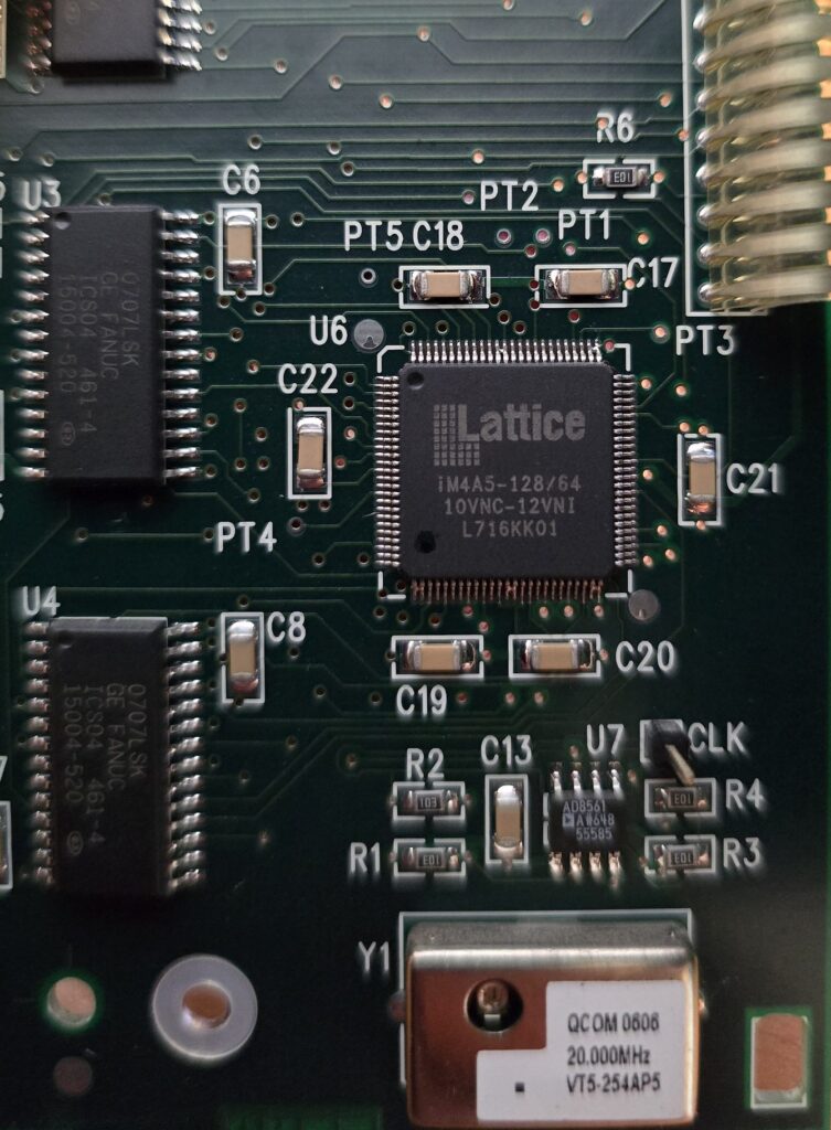
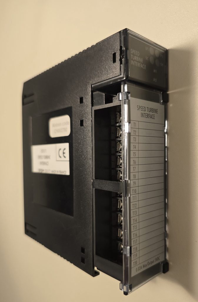
ICSS test platform — STI171 speed-measurement module for P320 TGC
Context
A customer needed to replace an STI171-1 board configured with 3/60 prescaling ratios, while only STI171 boards in the 3/100 version were available. Existing documentation did not clearly establish whether the two references also had hardware or functional differences.
As the manufacturer no longer supplied the corresponding firmware or source files, replacement could not be achieved by simply reprogramming the board from an official file.
In the ALSPA P320 TGC application, information from the STI171 is processed by the CCAD SC1STI171_DR block. It uses both measurement channels and accounts for the number of teeth on the phonic wheel, the DIV1 and DIV2 ratios and associated timing parameters, including TDIV and TDIVHY. The required compatibility therefore concerned both the board firmware and its operation with the existing Controcad logic.
Resolve the uncertainty between STI171 and STI171-1
ICSS compared the references, boards, their components and hardware code, then sought confirmation from former contacts at the manufacturer. This established that STI171 and STI171-1 used the same hardware and that no other functional modification had been identified between the two variants.
The relevant difference lay in the firmware of both CPLDs and in the second prescaling ratio: 100 on the available board, compared with 60 on the required variant. Prescaling by 3 had to remain unchanged.
Read and disassemble both CPLDs
The JEDEC files were read directly and reproducibly from both Lattice ispMACH CPLDs on the board. Because the firmware was not protected, the legacy development chain could be reconstructed using MACHXL 2.1, after which the files were disassembled to recover the logic equations, prescaling counters and channel-specific assignments.
This analysis separately identified the divide-by-3 and divide-by-100 functions without having to recreate all of the board logic from scratch.
Modify only the required function
The modification was limited to the counter providing divide-by-100 prescaling, which was replaced with divide-by-60 prescaling. Divide-by-3 prescaling, all other logic functions and I/O assignments were retained.
The DIV1 and DIV2 parameters in the CCAD block do not reprogram the CPLDs: they describe the ratios that the application logic must use to interpret the measured frequency correctly. Perfect consistency between the modified firmware, physical prescaler selection and SC1STI171_DR block configuration was therefore essential.
This targeted approach reduces risk compared with a complete rewrite: the board’s established behaviour and interface with the TGC application remain unchanged outside the function explicitly required.
Rebuild files compatible with the original tools
New JEDEC files were generated in a format compatible with the legacy programming chain, then checked by comparison and logic simulation before being loaded into the CPLDs.
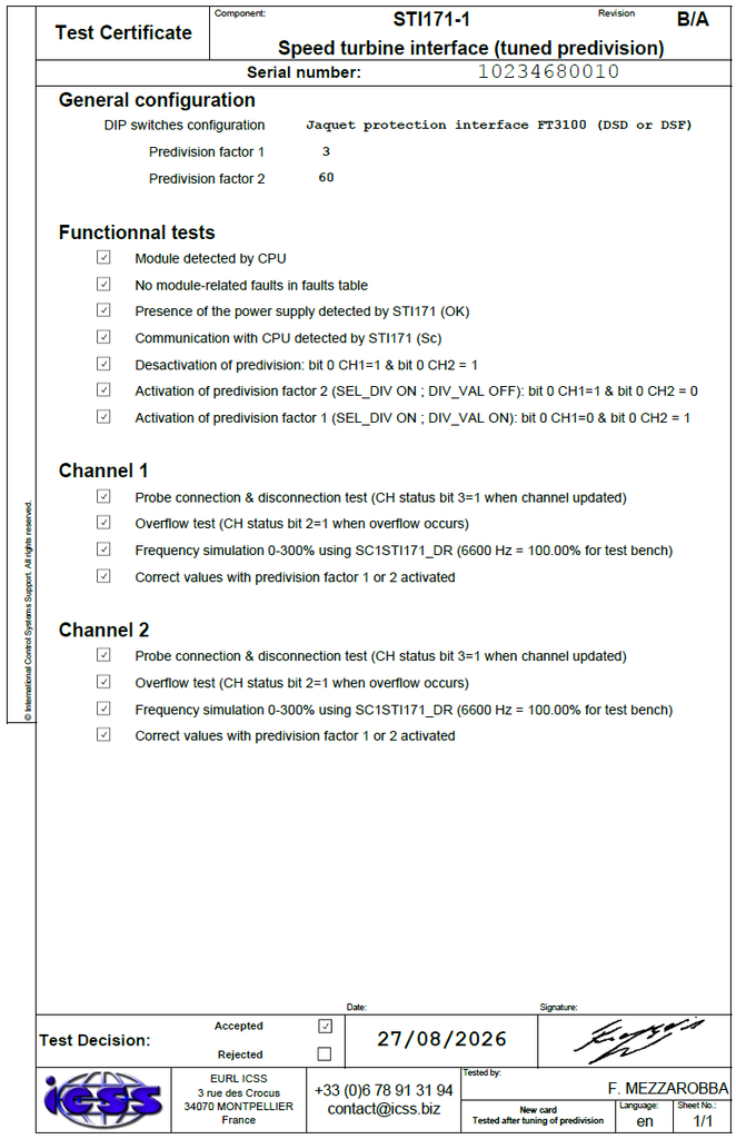
After reprogramming, the board underwent complete functional requalification on an ALSPA P320 TGC test platform. Switch configuration, intended for a Jaquet FT3100 DSD or DSF protection interface, was checked with prescaling factors of 3 and 60.
General testing verified:
- Detection of the module by the CPU.
- Absence of any board-related fault in the fault table.
- Correct detection of the power supply by the STI171.
- Communication between the board and CPU.
- Reported states when prescaling is disabled.
- Selection of each prescaling factor and consistency of the corresponding status bits.
Both channels were then qualified separately. For each one, testing covered probe connection and disconnection, overfrequency detection, and simulation from 0 to 300% using a frequency generator. Measurement processing was performed by the CCAD SC1STI171_DR block, configured so that 6,600 Hz represented 100% on the test platform.
Calculated values were checked with both prescaling factors. All tests on channels 1 and 2 were accepted and recorded in an individual test certificate linked to the board serial number.
Result and added value
The value of this work does not lie in a simple parameter change. It required resolving uncertainty between two references that had become difficult to document, recovering the programming architecture of legacy components, reconstructing their logic without source files and then modifying only the necessary function.
Validation was not limited to isolated CPLD operation. The reprogrammed board was fully requalified in its ALSPA P320 TGC environment, from measurement inputs and diagnostic functions through processing of both channels by the CCAD SC1STI171_DR block.
This reverse engineering therefore recreates an unavailable STI171-1 variant from a hardware-identical STI171 board and extends the operating life of ALSPA P320 TGC equipment without hardware replacement.
Restore the one-minute pulse of a virtualised Centralog
Development of a hardware and software chain converting a 24 V industrial pulse into a serial synchronisation event that can be used by the MTX Kernel of a virtualised Centralog Series 5 system.
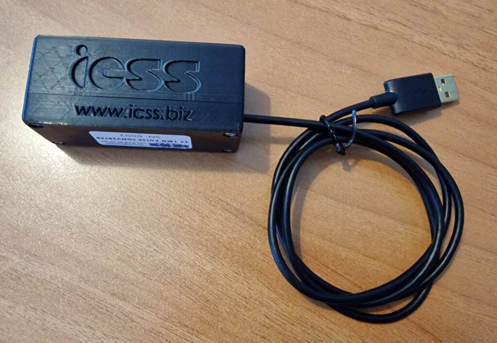
Bluewaters (Collie, Australia) — Virtualised ALSPA Centralog 5.7.2 (Windows XP)
Context
A hypervisor can redirect a physical serial port to a virtual machine. This generic function was not sufficient to preserve the Centralog one-minute pulse: the plant signal was a 24 V industrial pulse from a current loop, whereas the MTX Kernel expected a particular event on its serial port.
The electrical pulse therefore had to be converted, transmitted to the Windows XP virtual machine, and then recreated with the expected duration as the serial signal interpreted by the MTX Kernel as an external synchronisation pulse.
Simple serial-port redirection did not perform these conversions and could not reliably reproduce the complete functional chain. The solution had to preserve the legacy timing behaviour without retaining an old physical computer solely for this function.
A complete chain developed by ICSS
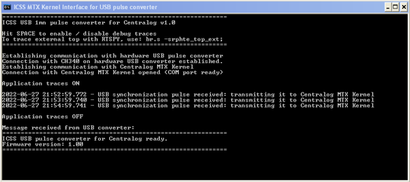
- A dedicated electronic interface adapts the 24 V industrial pulse, transmits it to the microcontroller and provides a visual indication of its receipt.
- The embedded firmware detects and filters the signal, controls the LED, transmits the pulse over USB and identifies the converter version.
- A Windows XP application developed by ICSS receives each USB pulse and recreates the serial signal with the precise form and duration expected by the MTX Kernel.
- Virtual serial ports connect this application to the virtualised Centralog while preserving operation of its legacy interface.
- An installer automatically configures the software components, required ports and application start-up within the Centralog environment.
This work therefore involves much more than adding a simple USB converter. ICSS designed and integrated the entire required chain, from the 24 V industrial input to the synchronisation event processed by the MTX Kernel, combining electronics, firmware, Windows software and in-depth knowledge of ALSPA Centralog.
Firmware and compatibility maintenance
The converter firmware was developed specifically for this application. It detects the pulse, provides debounce filtering, controls the LED and sends the serial message to the Windows application.
At each start-up, the converter also transmits its identification and firmware version. This information can be displayed in the application after power cycling or hardware reset. The microcontroller’s Wi-Fi is explicitly disabled in the version used.
The application monitors both serial links and automatically attempts to restore them if the USB converter or port associated with the MTX Kernel is disconnected.
End-to-end diagnostics
The solution was designed so that a failure can be located quickly without special instrumentation.
- The LED confirms that the converter has received the 24 V pulse.
- The application displays the status of its connections to the converter and MTX Kernel.
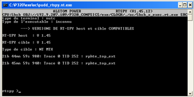
- Enabling traces verifies receipt of every USB pulse and its retransmission to Centralog.
- The firmware version can be read directly from the application.
- The RTSpy command br.s -srphte_top_ext; confirms that the external event is actually received by the MTX Kernel.
The chain can therefore be checked sequentially from the 24 V input through to the Centralog kernel.
Result
The legacy Centralog one-minute pulse was retained after virtualisation without depending on an old physical computer. The solution reproduces the serial signal and its timing as expected by the MTX Kernel, while providing diagnostic facilities that were absent from the original chain.
This development illustrates ICSS’s ability to address every aspect of an unusual problem: understanding the internal operation of ALSPA Centralog, adapting a 24 V industrial signal, electronics, embedded firmware, USB and serial communications, Windows XP integration, and validation in the MTX Kernel. It provides a maintainable response to a specific requirement that no standard product covered in full.
Are you experiencing a similar problem? Contact ICSS to determine whether existing field experience or a proven method can accelerate diagnosis and resolution.