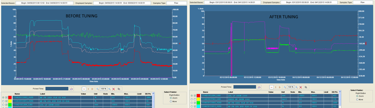
 HRSG drum level regulation – tuning
ICSS has deep experience in regulation, including but not limited to:
- Boiler regulation (3 elements drum level control, double-stage desuperheaters, switch-over of control valves…)
- Water Steam Cycle regulation (bypasses, water injection, variable-speed feed-water pumps…)
- Speed control, pressure control, flow control, level control ; enthalpy / temperature control, etc.
Thanks to our knowledge in industrial processes and combined cycle power plants, we are able to suggest, design, implement, test, monitor and tune new regulation concepts or concepts already implemented on similar projects.
We are able to implement advanced regulation strategy, using cascaded or parallel PID controllers as well as feed-forwards or similar strategies related to our process knowledge.
*
* *
References:
-
Kwinana (Perth, Western Australia) – KA13E2 combined cycle (320 MW)
Modification of the HRSG drum level control logic, on a running unit.
New logic has been implemented with an enable / disable flag, controllable by the operators, to change the concept of the drums feed-water control valves (2 valves per drum: “30% flow” and “100% flow”).
Prior to intervention, 4 different PID controllers were used, driving the two control valves independently:
- 1 PID for the 1 element controller (mm to % opening), driving only the “30% flow” control valve.
- 2 PID for the flow part (kg/s to % opening) of the 3 elements controller, one for each control valve.
- 1 PID for the level part (mm to kg/s) of the 3 elements controller, sending his output to the 2 PID used for the flow part of the 3 elements controller.
With such logic, when the 3 elements control wasn’t operational, the 100% control valve wasn’t opening at all. In case of startup with discrepancy on the steam flow-meters, the unit could trip due to limited feed-water flow.
A new logic has been implemented, using only 3 PID controllers to generate a global demand, common to the 2 control valves:
- 1 PID for the 1 element controller, generating the 1 element global set point.
- 2 PID for the 3 elements controller (flow and level), generating the 3 elements global set point (in tracking on the 1 element controller).
Then, additional logic has been implemented to allow a bump-less switch-over between the two control valves. The operator is still able to drive manually the global opening command.
We took as well this opportunity to implement various improvements:
- The 3 elements level controller tracks measured flow difference (steam flow – drum feed-water flow – desuperheaters flow) during feed water pump switch-over or when the feed water pressure limiter is active.
- The 3 elements flow controller tracks the global output of the control valves when 3 elements control is disabled, during feed water pump switch-over or when the feed water pressure limiter is active.
- The 1 element controller tracks the global output of the control valves when the set point station is in manual mode.
- The 3 elements control is disabled when one of the control valves is in manual or when flame off is detected.
- The pressure relief control is acting directly on the global set point of the control valves (forcing both low limit and high limit to 15%).
- The pressure limiter upper limit is now set to the current global control valve opening value for 1 second when the pressure goes below the set point (for faster action).
-
Tzafit (Kfar Menahem, Israel) – KA26 combined cycle (2×435 MW)
Commissioning and tuning of HRSG / WSC regulation loops.
-
Niehl 3 (Cologne, Germany) – KA26 combined cycle (450 MW) with district heating
Commissioning and tuning of HRSG / WSC regulation loops.
Design, implementation, commissioning and tuning of a new concept for the HRSG desuperheaters.
We identified two main issues with the original design:
- The initial concept for the inter-stage desuperheater (located before the final super-heater) was to react very slowly, trying to minimize the temperature difference before and after the final stage desuperheater (located after the final super-heater). The final stage was supposed to react quickly, to control the temperature at the outlet of the HRSG, and the inter-stage to open slowly over time, allowing the final stage to close. The inter-stage desuperheater was actually never fully closing during operation, we were spraying water all the time, and this concept was not working as well for the huge transient that we can expect on an HRSG. The steam turbine stress was going extremely high during low-load operation, and the steam turbine was tripping unless the desuperheaters were controlled in manual mode.
- The project was using variable-speed feed-water pumps, but this was not properly taken in account in the desuperheating concept. In some cases, during transient operation (low drum pressure and fast increase of the GT load), even with both desuperheaters fully opened, the temperature was increasing too much. An additional control had to be implemented to control the feed-water pressure in such case. As well, the feed-water pressure value had to be taken in account for the calculation of the PID controllers parameters.
We changed the design for this regulation loop:
- An new calculation has been implemented to elaborate the temperature set-point (at the outlet of the last super-heater) for the inter-stage desuperheater (before the final super-heater):
- The maximum value was 588°C in all cases (there is a 5-mn delayed PLS if the temperature reach 600°C to protect the piping after the outlet of the final superheater), and the minimum value 450°C . The maximum steam outlet temperature set-point is 585°C so, basically, when we want to regulate 585°C, we are doing it with the final stage and not the inter-stage.
- When the steam outlet temperature set-point (global for both desuperheaters) was less than 555°C, the set-point for the inter-stage desuperheater was set to 565°C (in order to avoid using intensively the inter-stage desuperheater, and to limit the amount of time spent spraying water with the inter-stage). In case of fast increase of the GT load, the inter-stage had then to be more reactive.
- When the steam outlet temperature set-point was more than 555°C, the set-point for the inter-stage was set to 10°C more (to be able to regulate properly the final temperature, we want to do it with the final stage – the inter-stage should just participate, unless were are close to the temperature limit at the outlet of the final super-heater).
- When the final stage desuperheater is opened more than 75%, a PID controller is lowering the set-point of the inter-stage desuperheater. We actually only saw this PID controller in operation on the reheat steam, which is cooled by IP/LP feed-water with a much lower pressure.
- As we wanted to limit the time spent spraying with the inter-stage, as we could work close to the temperature limit at the outlet of the final super-heater, and as the GT load could change very quickly, the inter-stage had now to react faster:
- The PID loop parameters have been tuned.
- The PID loop parameters have been dynamically adjusted according to feed-water pressure and the steam pressure.
- The PID parameters of the inter-stage desuperheater have been dynamically adjusted in case of high discrepancy between temperature set-point and measurement (transient operation, when the inter-stage isn’t stabilized yet).
- Feed-forwards have been implemented on the inter-stage desuperheater for transient operation:
- When the temperature at the outlet of the final stage is more than the set-point + 5°C, we open the inter-stage for a percentage based on the temperature discrepancy and on our process knowledge, and we decrease the set-point to allow the PID controller to catch up quickly. As well, we start giving flow demand to the feed-water pump (temperature to bar demand conversion). This demand is then decreased slowly over time, as the feed-water pump has to reacts slower than the control valves, which can decrease their opening if required.
- When the temperature at the outlet of the final stage is more than the set-point + 5°C for more than 10 seconds, we open the inter-stage for a percentage and time based on the temperature discrepancy and on our process knowledge (pulsed command), without changing the set-point.
- If for any reason the temperature at the outlet of the final stage becomes more than the highest-controlled value (588°C + 2°C = 590°C), we send a pulsed command to the inter-stage for a percentage and time based on our process knowledge. We start also increasing more aggressively the flow demand to the feed-water pumps (1,5 bar / °C). This logic was actually never triggered, but was implemented to avoid a possible PLS during testing.
- If for any reason the temperature at the outlet of the final stage becomes more than 600°C, we increase the speed of the feed-water pumps to the maximal value.
- Feed-water demand will come as well when the inter-stage is opened more than 98%. In such case, we are controlling the temperature at the outlet of the last super-heater with the feed-water pump (without waiting for the temperature to overshoot the set-point for more than 5°C).
Many other parameters have been tuned during operation, such as control-valves switch-over for the final stage and PID parameters.
After implementation of this new logic, temperature regulation was much better during normal operation.
The inter-stage was opening only when required, avoiding spraying water for no reason and improving the final temperature at the outlet of the HRSG.
Low-load operation was a big issue before, steam turbine stress was going high and manual operation was necessary to avoid a steam turbine trip. After implementation of this new logic, the HRSG was able to follow properly the request from the steam turbine, even when the gas turbine was going up or down. Low-load operation was always reached earlier than expected, with minimum stress.