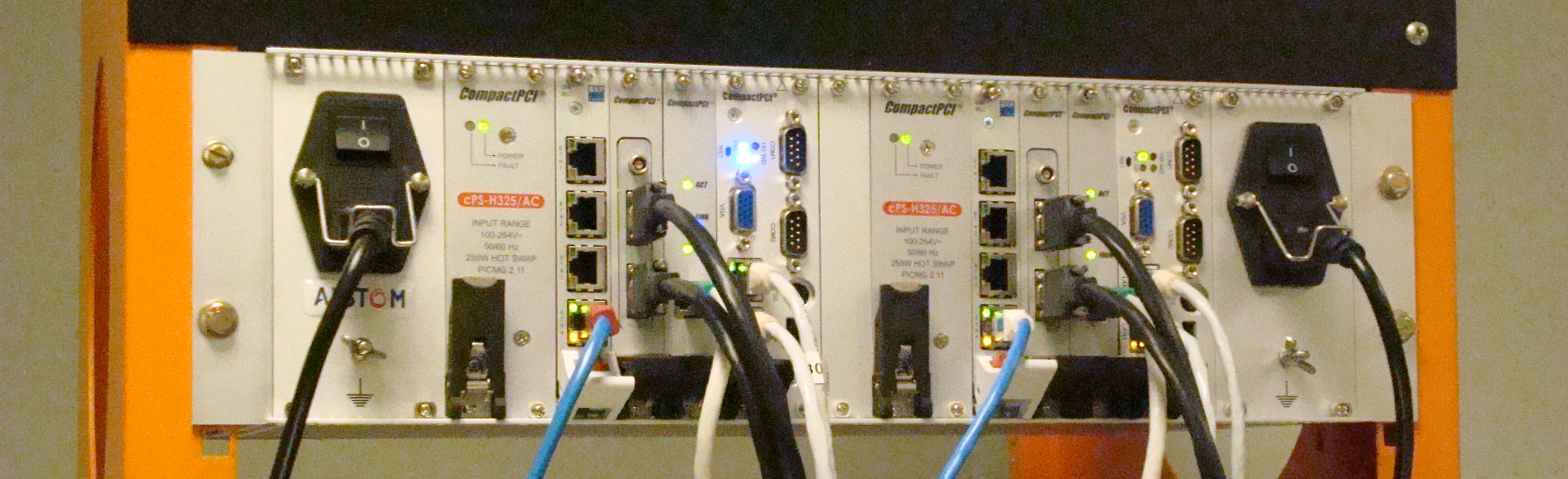
 MFC3000 controller, used on Alstom Alspa P320 S6 DCS
Generalities
Alstom (originally CEGELEC) implemented several automation and control solutions, based on:
- Third-parties PLCs (GE Fanuc, B&R automation ; AdLink), often with customized system-layer (GE Fanuc 90-30 C80-35 ; GE Fanuc 90-70 C80-75 ; GE Fanuc Rx3i ; B&R automation APC620 MFC1000; AdLink MFC3000 ; B&R automation X20 CE1000 ; B&R automation X20 CE1500 ; ICS Triplex Trusted CE3500).
- Alstom’s designed PLCs (Controbloc T20 ; Controbloc N20 ; C350 ; C370 ; CE2000 ; CE3000).
- Standard Ethernet network, with or without customized protocol: field network EPL, unit networks S-8000 E900 and S-8000 E920.
- Industrial FIP network: field network F-8000, unit network F-900.
- Alstom’s designed supervisor stations, running on various targets: Centralog, renamed later on Alspa HMI, which evolved over time and series: Centralog VME, Centralog Unix, Centralog Windows, Alspa HMI. Obsolescence of hardware (VME racks, Sun stations) decreased the utilization of the first series, many projects having been retrofitted to new versions. Centralog Windows (starting from Series 5) can now be executed on virtual machines.
- A global engineering tool, used or not depending on the projects (machine control or distributed control system), Controcad. Many different versions of Controcad exists. It was initially only running under Unix, and became a Windows program since version 3 of Controcad.
The name of automation and control solution provided by Alstom can be changing depending on the application (machine control or distributed control system), we can see for example:
- For Steam Turbines controllers: TGC820 ; P320 TGC V1 ; P320 TGC V2 ; P320 TGC V2+ ; Alspa ControSteam V3 ; Alspa ControSteam V4E (the ABB controller Turbotrol is used a lot as well on Alstom projects, interfaced with Alstom DCS).
- For Gas Turbines controllers: Alspa ControGas V3. It’s actually initially a clone of the logic implemented on ABB controller Egatrol, used on Alstom gas projects before Alstom developed his own gas turbine controller.
- Excitation solutions: AVR820 ; AVR820E ; AVR920 ; P320 AVR V1 ; P320 AVR V2 ; Alspa ControGen…
- Global labels, referring to the entire DCS: Alspa P320 S4 ; Alspa P320 S5 ; Alspa P320 S6 ; Alspa ControPlant…
Alstom’s automation solution Alspa P320 is mainly used on power plants:
- Distributed Control System (conventional plants, combined cycle, renewable).
- Machine control: Steam Turbine or Gas Turbine.
- Rarely, automation for only one part of the plant: AVR only for example.
The Controcad tool
The Controcad allow to interact with all the components of the Alspa DCS.
Most often, DCS contains PLCs, softwares to program these PLCs, specific supervisors, openness through communication protocols, without something to really manage all these parts together. Controcad offers a different approach, an higher level of management.
The approach has good points (an export of a Controcad project contains all informations, coherency control alerts the engineer when he made a change somewhere in the DCS and forgot about making it somewhere else, Controcad is often doing such changes automatically by himself, most of the changes in the logic can be made and loaded using only one tool, exchange management is automated, and so on) as well as some bad points (coherency changes triggered when modifying something or generating the code can take long time, basic changes on mimics have to be done inside Controcad then generated and loaded, the same has to be done when modifying for example alarms or variables labels, the system is quite complex and a system engineer is often useful to be able to take its full benefits, and so on).
A Controcad project contains two main parts:
- Files
Contains mimics, libraries and basic functions, PLC folders (code already generated), debug informations, files used by third-party applications interfaced with Controcad, some specific parameters: configuration of Profibus networks, configuration of CSS-G gateways, configuration of some PLCs not fully interfaced with Controcad and are programmed and loaded using a third-party tool (for example Boiler Protection System based on Trusted CE3500), documentation and associated templates… - Database
Contains the full configuration of the project, all the variables and exchanges, functional blocks configuration, supervisors’ configuration and supervision data, all the logic diagrams before conversion to code, and many other data and informations.
The Controcad, running under Oracle, can be acceded (read / write mode) by any SQL client being able to connect to Oracle. It’s possible, quite easily, to perform mass-changes inside a project by running scripts (for example, shift all the AND gates of the project one column to the left, apply a generic change to the labels of all the variables produced by a specific block, consumed by another and used in supervisors, and so on). It’s possible as well to merge several Controcad projects into a single one, to export the full DCS configuration in order to perform a retrofit, or to compare the logic and setting values of two different projects by connecting at the same time to the two databases. The Controcad database is unique in the DCS business, and thanks to this openness it’s possible to perform on Alspa systems some applications that can’t be done on other manufacturers system. However, the knowledge of the database internals is a must. Don’t hesitate to contact us about this if you have a specific requirement.
All the components of the DCS (PLCs, networks, supervisors, links with externals systems, clocks, and so on) is most of the time (some particularities exists) defined inside the hardware tree (Hard) of the project. We can find as well inside the hardware tree, the different workspaces, the execution order of the PLCs programs, and so on.
The automation blocks are defined inside the libraries tree (Lib) of the project. Automation blocks can be written using LEA (Langage Elaboré Automatisme), or using FBD (Function Blocks Diagrams) which will be converted automatically to LEA (inside Controcad, all the diagrams are exported in LEA format when saved). Automation blocks can call other blocks as well as sub-functions (basic functions), which can be written in LEA or in C. The Basic Function Editor tool allows to compile easily these sub-functions for the different targets managed by Controcad.
All the logic (links between automation blocks coming from the libraries) is defined inside the functional tree (Fct), as Function Blocks Diagrams. During code generation, if a diagram is associated with a PLC (through the Program Operative Units, POU), it’s copied (as read-only) inside the hardware tree and an address is affected in the target PLC for all the variables in use. Function Blocks Diagrams can be as well generated for simulation, directly inside the functional tree. Project documentation can as well be configured and automatically generated from the functional tree.
The treatments performed by the supervisors is configured inside the HMI tree. We can find here the configuration of the face plates, synthetic variables, mimics definitions, alarms, and so on.
The mimics themselves as well as the sub-drawings used inside and the alarms sheets are managed from the views tree. The DV-Draw editor can be called from the views tree in order to perform mimics modifications.
The variables grid (called from the functional tree) is used to change the configuration of the variables and the treatments associated with variables.
This organisation has good and bad points, as any interface. Since it’s possible to interact directly with the database to answer specific requirements, the advanced user can perform easily any kind of change.
Three kind of generation can be launched using Controcad :
- Code generation. Variables exchanges are created automatically by Controcad (some exchanges can be managed manually if required). Controcad try to keep the adresses of the exchanges already existing (several generation mode are possible, in case of online generation, an exchange already existing cannot be shifted to another address). The function block diagrams code and the automation blocks code is converted to C. The basic functions, already compiled, are called directly. The C code is then compiled by the compiler used by the target PLC.
- HMI generation. After coherency check, supervision data is exported as text files (.UO or .CSV files, depending on the versions). The Centralog CIS through the CCC application or the Alspa RTDS are in charge of interpreting these files.
- Mimics generation. Mimics, sub-drawings and alarm sheets are exported as archive after coherency check. The mimic viewer EXP or Alspa HMI is in charge of displaying the mimics contained in the archive on the operator’s stations.
The PLC program can be loaded inside the targets managed by Controcad using the Cell Loader tool, integrated with Controcad. It’s possible as well to use directly the tools of the PLC’s manufacturer (P80, Machine Edition, and so on). Using the Cell Loader allows coherency check of the automation cell, unit network, version management, and so on.